
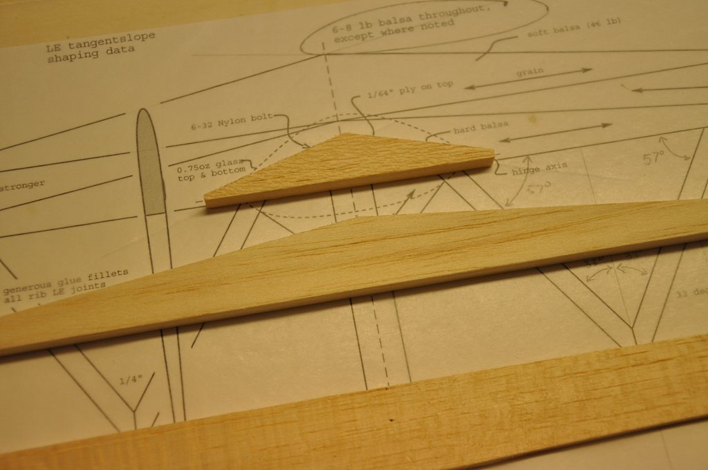
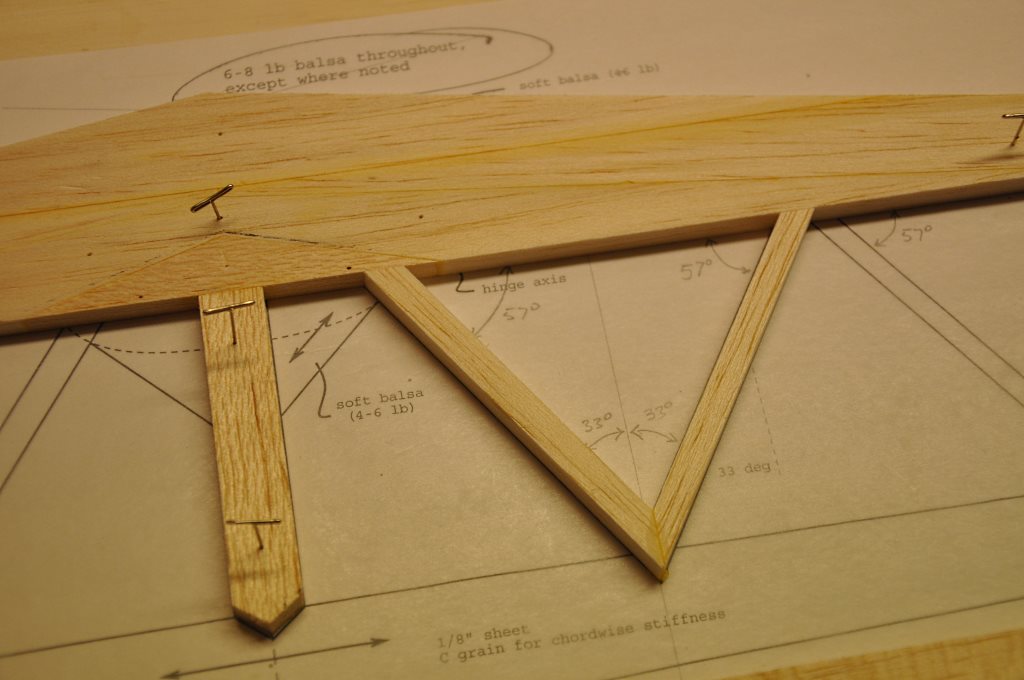
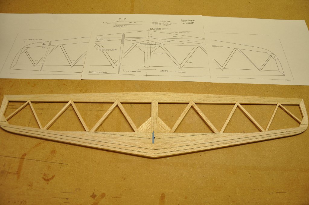
Important: Keeping the weight of the horizontal stabilizer to a minimum is one of the best ways to lower the over-all weight of your glider. Picking the right balsa is critical to your success here - due to the long arm of the tail surfaces, overbuilding them will necessitate useless nose weight being added before flight to bring the plane in balance.

Every other part of the stab is made from 1/4" stock.
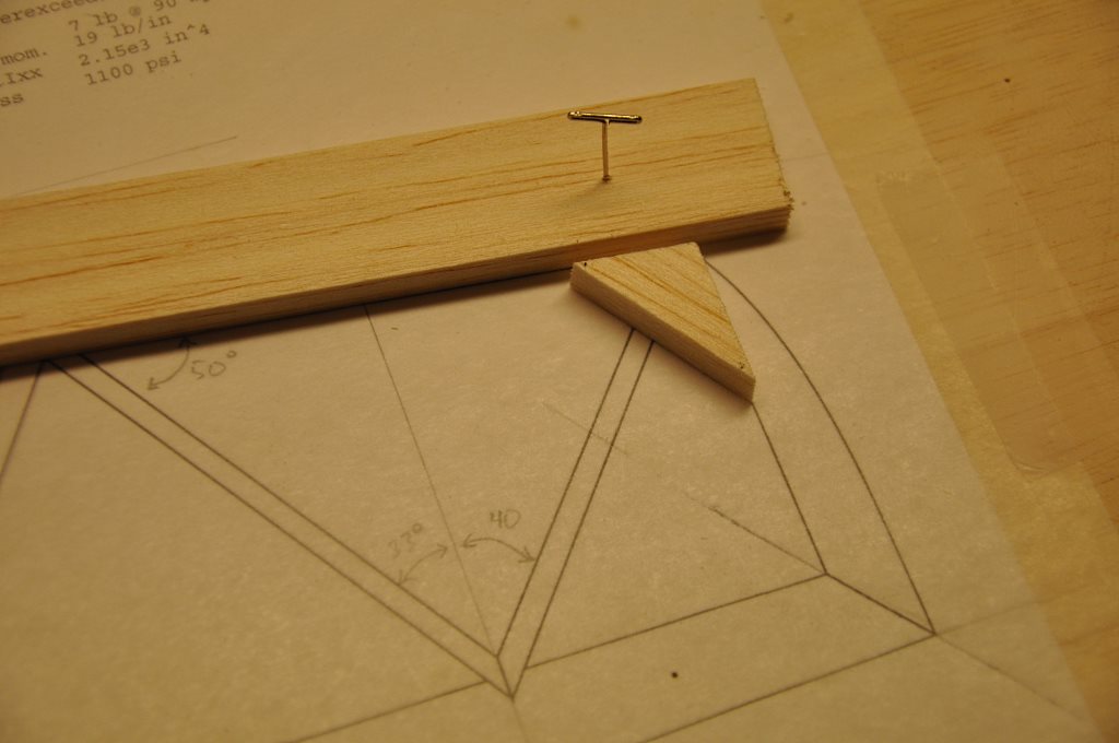
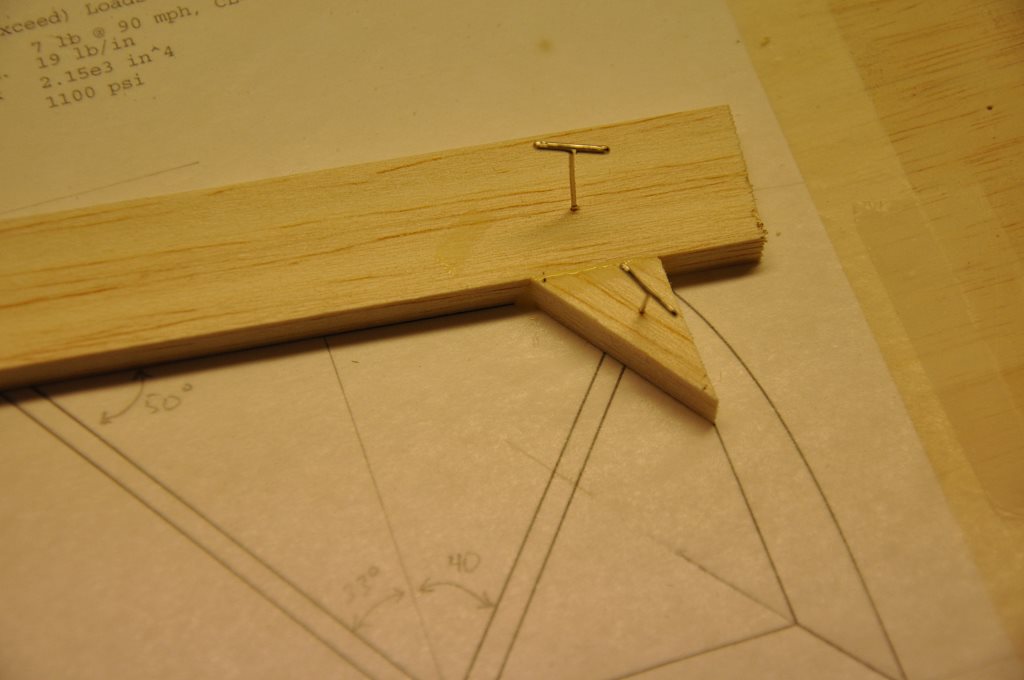
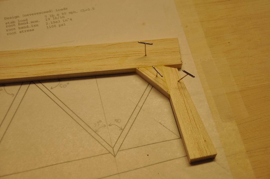
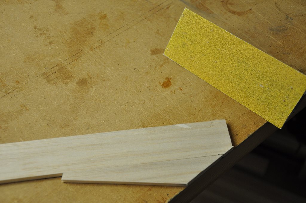
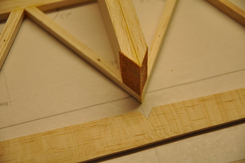
So this time I did not use the miter sander at all... Instead, I used the edge of my workbench.
I marked off the needed angle, placed the balsa at that agile, and then sanded using the edge of the table - much quicker and dead accurate!
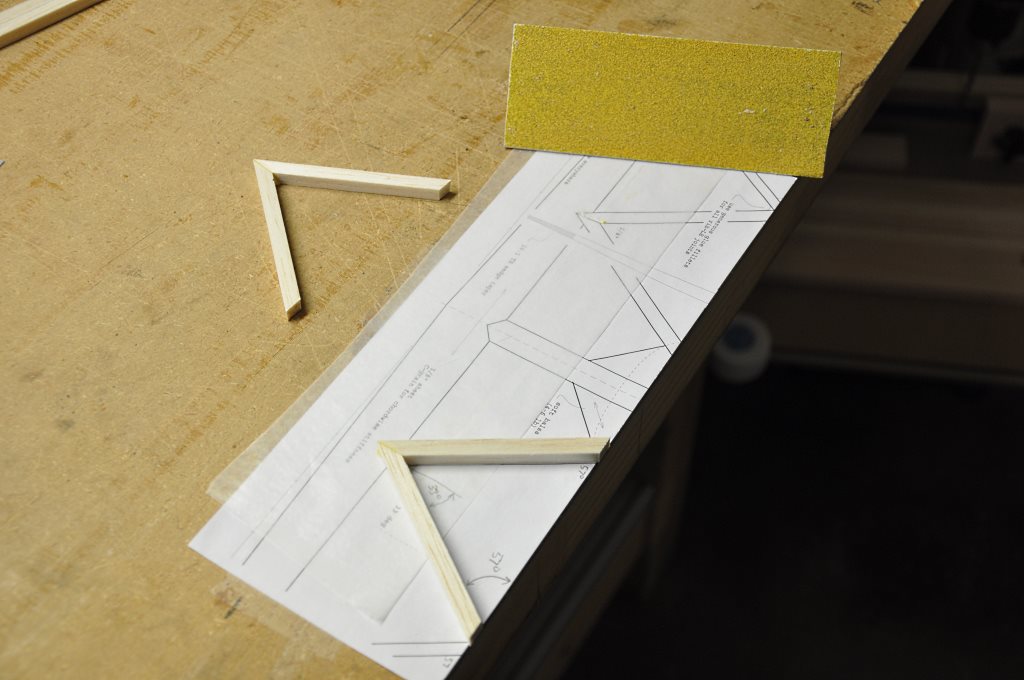
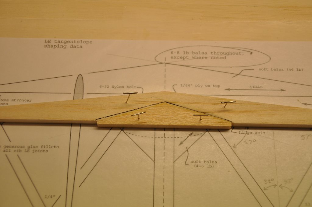
You can see here that I printed out a copy of the stab plans, trimmed it to the needed joint and sanded the ribs to the joint.
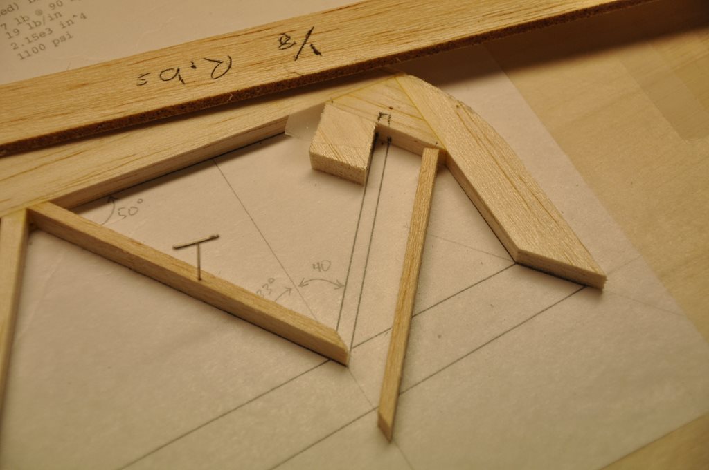
I set up a small block to act as a bearing surface for my sanding stick. I also marked on the corner, how far the notch needed to go.
I then sanded the notch.
This is a time-consuming and very tricky process as you need to get all the notches at just the right depth and location.
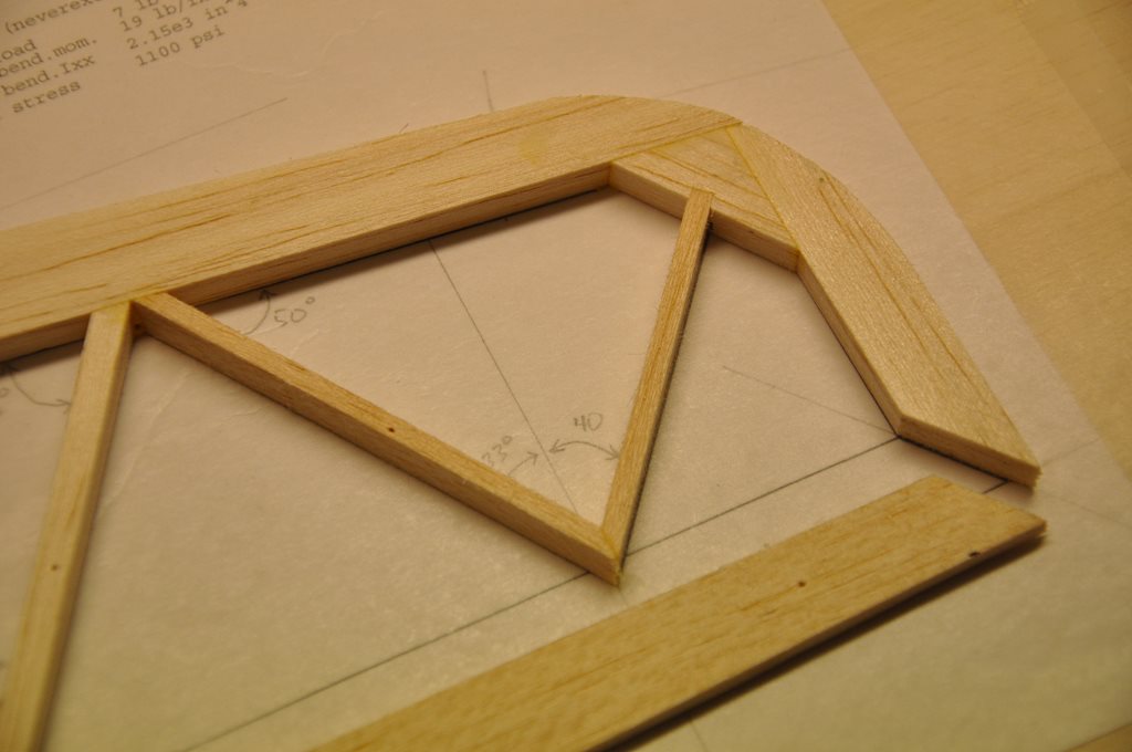
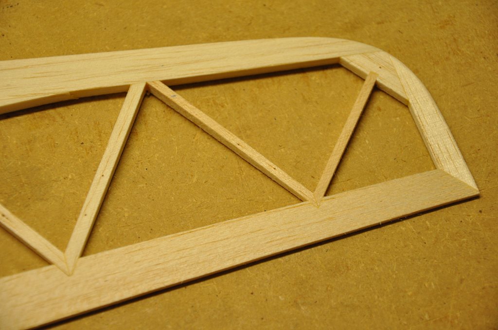
To simplify this process, I created a task specific sanding block by making a "V" shaped block that matched the trailing edge of the ribs.
I then sanded the required notches into the trailing edge.

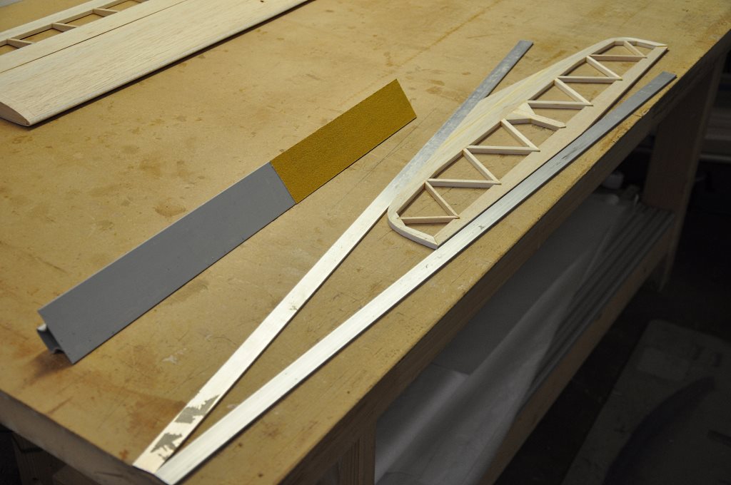
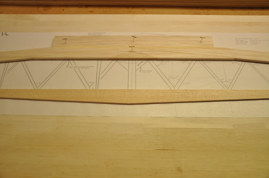
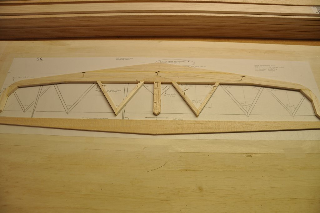
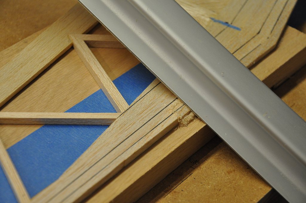
The process for shaping the stab is the same as used for the fin and rudder. I used long bars to align the tapered edges of the stab the proper distance from the edge of the table.
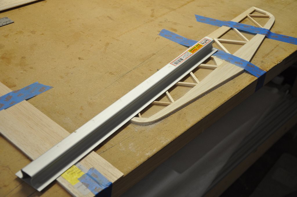
Because this distance was longer than my sanding bar, I actually used a 3/32 inch shim halfway between the table edge and the end of the stab instead of a 1/8 inch shim at the table edge as described in the plans.
I then sanded the taper until the sanding bar started grazing the blue tape.
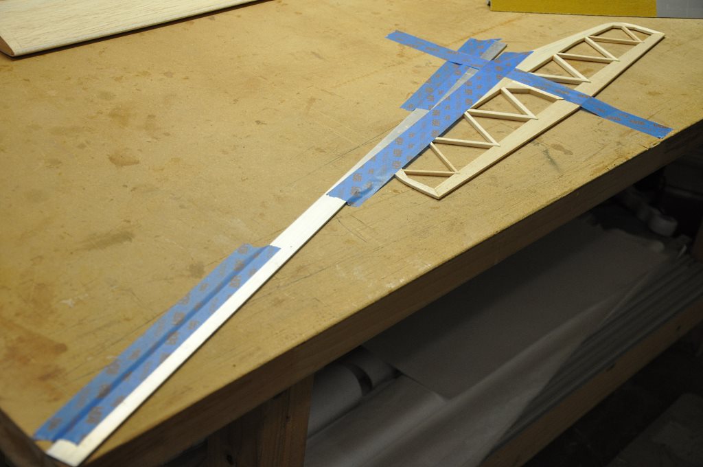
Once one side was done, I flipped the stab.
This time instead of no shim, I used a 1/16 inch shim at the half-way location - again, only because my sanding bar couldn't reach all the way to the edge of the table.
I then sanded as before until the taper reached the root.
At this point the stab was shaped span-wise, but still needed to have the HT-21 airfoil shaped into it chord-wise.
As with the fin, I marked off the 5%, 10%, and 25% chord lines onto the stab. Since the airfoil is symmetrical, I made these marks top and bottom.
I set my stab on the oak block that I've been using for these sanding operations, and place the block at the required distance from the table edge to achieve the prescribed slope.
I then sanded up to each line. I did all the 5% (2.7:1 slope) first, then changed the block to the 10% (8.5:1 slope) position and did all those angles. Finally, I flipped the stab around and sanded from the trailing edge to the 25% line to shape the rear part of the airfoil.
Just as a refresher, to achieve these slopes, if you had a 1 inch board - you'd simply set the front of your board 2.7 inches from the table edge. In my case I had a 3/4 inch board, so I multiplied all my slope numbers by .75 and that's how far back I set the board.
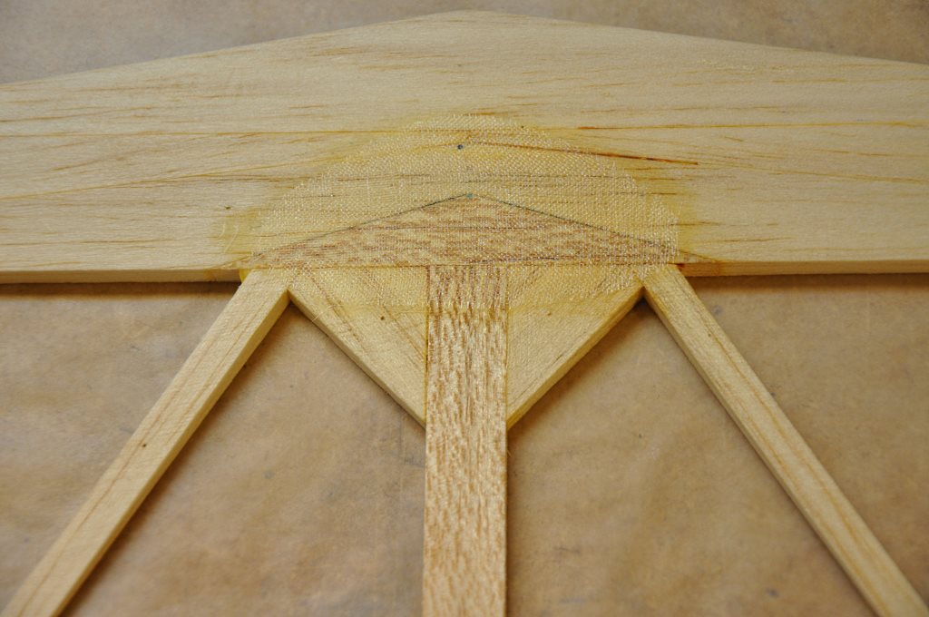
I brushed on laminating epoxy that I first thinned with some alcohol - unfortunately, the epoxy ran a little and kind of made a discolored mess on the balsa - oh well!

I marked out the location of the slot, and carefully cut and sanded out the slot until the mount
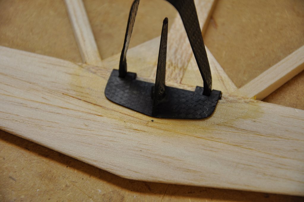
Once the mount is properly located, I can mark the location of the screw hole and drill it in the stab.
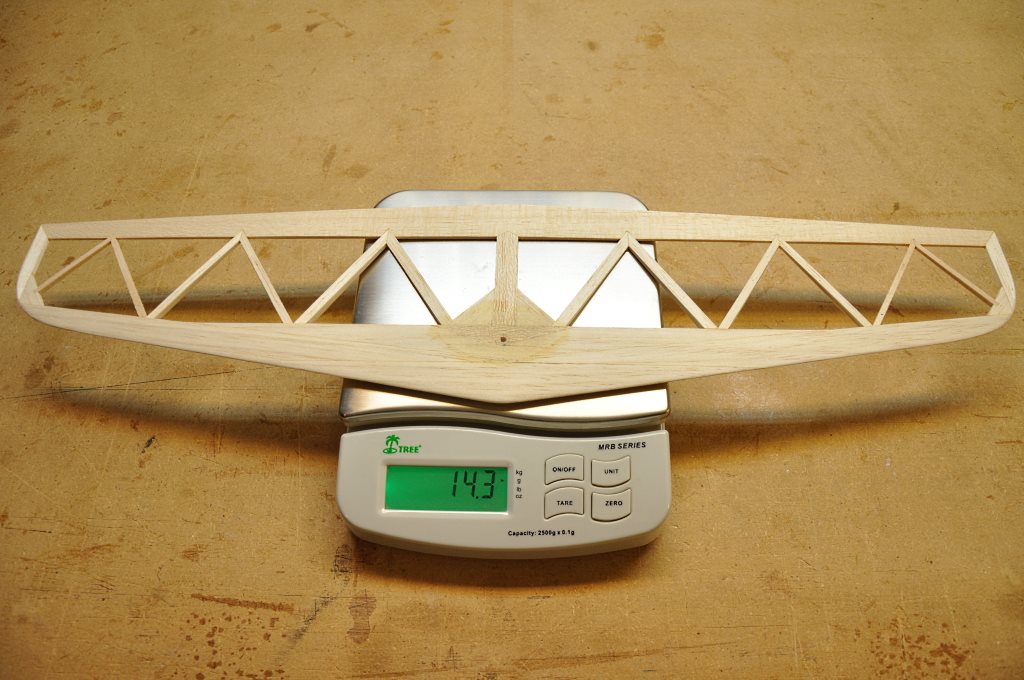
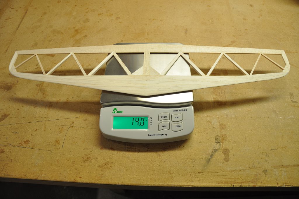
Looks like I could have picked just slightly heavier balsa to meet the target weight. - While having the stab be so light is nice - the down-side is that it might be a little weak... I'll have to see how it does.